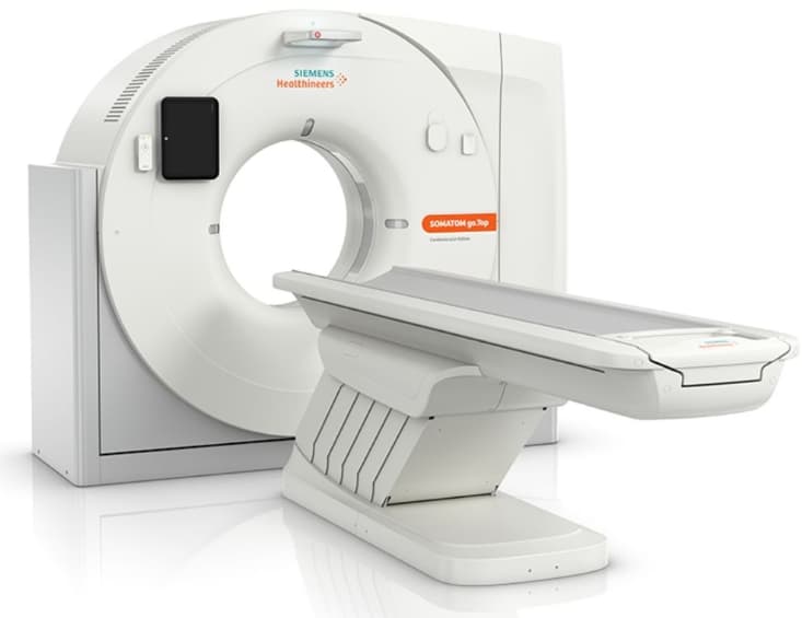
As a biomedical equipment technician who services Siemens medical imaging equipment, one of the most common calls I receive is for a customer’s SOMATOM.All CT scanner that fails to power up.
This versatile 64-slice mobile CT is popular for bringing quality scans directly to patients, but that mobility means it can experience bumps, bangs, and power issues that fixed install scanners may avoid.
Siemens SOMATOM go.All CT Scanner Not Turning On
When my troubleshooting phone rings with “my SOMATOM CT won’t turn on,” there’s no need to panic.
These machines seem intimidating with their spinning gantries and intricate electronics, but I’ve learned a systematic approach can usually get them humming again quickly. Here’s my plan of attack when facing a lifeless SOMATOM.
Initial Troubleshooting Questions
Before grabbing my toolkit, diagnostics laptop, and schematics, my first move is gathering critical information by asking the customer some key questions:
- Has anything happened recently like the scanner being bumped during transport or a power outage?
- Were staff doing anything out of the ordinary with the system right before the issue arose?
- Have any error messages or codes appeared on the screen?
- Does any part of the system still have power (lights, fans, etc)?
Seemingly small details like these provide clues to the underlying cause. I also checked the system’s maintenance logs – a discrepancy found during the last PM could very well be related.
External Power Checks
Assuming there are no obvious red flags from my initial interview, I systematically work through various power checks, starting outside the scanner:
- Verify the power cable is fully seated in the outlet and inlet. It sounds simple but I’ve seen loose connectors cause all kinds of havoc.
- Check the wall outlet, power strip, and breaker supplying power aren’t faulty.
- Confirm the external power switch didn’t accidentally get bumped off.
- Check the inlet voltage with a multimeter. Depending on the model, SOMATOMs require 200-240 volts AC to operate normally. Too high, low, or unstable power can prevent system startup.
If all external supply checks pan out, it’s time to open ‘er up!
Internal Power Distribution Tracing
Once inside the gantry, I focus on verifying proper power distribution from the main inlet through various protective devices like fuses and contactors before reaching the vulnerable printed circuit boards (PCBs):
- Check correct voltages are present at the CUP and LPU PCBs. These interface with system electronics and safety controls.
- Verify continuity through fuses and no sign of burns/corrosion.
- Confirm contactors are energizing to pass power downstream.
- Check cable connections are secure with no damaged wires or pins.
If power looks solid coming into the PCBs, it’s likely an electronics issue. If power drops out somewhere upstream, I trace back to find the culprit device.
Common Power Pitfalls
Some patterns I’ve learned over the years troubleshooting these temperamental SOMATOMs:
- Power surges can destroy fuses, PCBs, and other components.
- Failed cooling fans lead to overheating and system shutdown.
- Jiggled-loose wiring during transport causes intermittent power loss.
- Leaky capacitors slowly fail until they prevent proper PCB operation.
So before condemning any big-ticket parts as outright failed, I check for secondary failures caused by smaller issues first.
Software Glitches
While many CT startup issues stem from physical components and connections, software can also be the unseen culprit:
- Corrupted firmware or OS files may prevent system boot.
- Bad parameter data writes may interfere with initialization.
- Faulty upgrades or patches can introduce new bugs.
- Virus infections or malware events could be disrupting normal CT operations.
If component-level troubleshooting draws a blank, it’s time to break out the malware scans, system diagnostics, and recovery tools.
The Importance of Bearings
Failure to spin up a CT gantry often ties back to the robust bearings that enable smooth and precise rotation under immense loads. When these complex assemblies get damaged or worn out, the restart process applies the highest mechanical stress, revealing underlying defects.
I inspect bearings closely for signs of:
- Broken or displaced ball bearings.
- Pitted races from electrical fluting.
- Cracked or bent housings.
- Loose set screws or end caps.
Catching small defects early prevents catastrophic failures down the road!
Stuck In Standby Mode
In some cases, a SOMATOM CT may appear dead when the electronics remain powered in low activity standby. They can enter this hibernation state under certain conditions like backup battery drain.
I reactivate standby systems by:
- Providing sufficient external AC power input.
- Charging or replacing the internal UPS battery.
- Pressing wake/restart control sequences dictated by the service manual.
This trick got me out of one nasty road trip years back!
The Dreaded Gantry Tilt Fault
If opening up a non-responsive CT reveals an angry blinking amber light on the gantry tilt indicator, prepare for some dilemma. This means the complex orientation sensors deep within the rotating frame detected an abnormal tilt exceeding parameters. It then locked the gantry down to prevent potential crashes.
Resetting tilt faults requires carefully:
- Leveling the gantry manually via the jackscrews
- Reseating gantry angle and motion position detectors
- Re-calibrating the tilt sensor alignment
The process is tedious but critical to get exactly right before allowing gantry rotation again. One wrong move risks thousands in damage!
In-Depth Power Distribution Analysis
The SOMATOM go. All require a complex power ecosystem to activate its rotating gantry, high voltage tubes, detectors, and processing electronics. Before declaring failure, I methodically verify:
- Voltage/phase readings at the wall outlet – Fluctuations can destabilize components.
- Breaker load ratings match current draw specifications.
- Power cabling gauge suitable for scanner-thirsty demands.
- Cable strain relief clamp integrity to avoid intermittent shorts.
- Reliable ground paths – loops/spikes destroy boards!.
- Primary side EMI filter performance – reduces electrical noise.
- Switching power supply ripple within acceptable bounds.
- Capacitor balancing across phases – no phase overloads.
- Gantry slip ring and brush contacts – robust signal transfer.
- LCD inverter operation if the display seems unpowered.
- Backup battery capacity for volatile memory retention.
I record all voltage, current, resistance, capacitance, and ripple readings for each subsequent stage, verifying conformance to service manual guidelines. Deviations pinpoint distribution issues. Only once the electrical ecosystem checks out do I dig into the electronics.
Firmware Debugging Methodologies
Corrupted firmware can certainly prevent system startup. To diagnose:
- Check the boot manager sequence for any halts.
- Review crash dump and syslogs for exception events.
- Pull any updated patches or installs for review.
- Dump and validate checksums across all image partitions.
- Inspect file allocation tables/directories for anomalies.
- Load recovery media for system restoration if needed.
- Use debug bridges to watch initialization routine behavior.
For deep firmware dives, some techs even solder physical bus analyzers like logic probes onto the PCBs to intercept traffic. This sobering reminder of the scanner’s complexity makes reimaging the operating system a tempting shortcut!
X-Ray Tube Warmup Sequence Verification
If phantom power problems are eliminated, the lack of high-voltage X-ray production prevents imaging. I take a methodical approach:
- Safely verify the tube housing vacuum using sealed test points.
- Activate filament heating; check the ammeter draw.
- Profile the high voltage ramp-up: smooth or jagged?
- Get output waveform baseline with an oscilloscope.
- Note any emission delay once 150kV is energized.
- Confirm rotating anode spin activated by control signals.
- Rule out false errors from beam sensors/alignment.
Insights here allow accurate service manual guided diagnosis – send the wrong tube back for “failure” and some finance guy gets upset!
Patient Handling Best Practices
Maneuvering sick patients onto the table seems outside a CT power fault, but safe movement minimizes crises like:
- Impacts on system gantry or detectors.
- Jarring/toppling causing tilt errors.
- Staff strains lead to human error.
- Poor connections if life support equipment falls.
So we establish robust protocols requiring:
- Motorized beds with precise height alignment.
- Team coordination with positioning.
- Doorway clearance for movement.
- Hallways are free of cords and clutter.
- Table load sensor recalibration.
- Periodic maintenance for carriers/lifts.
Follow guidelines and the patient handling dance avoids damaging downtime events!
Component-Level Fault Isolation
Tracking electrical issues back to individual failed parts requires meticulous PCB testing:
- Visual inspection for burnt resistors/capacitors.
- Multimeter continuity tests for broken traces.
- Load testing power regulator response.
- Checking crystal oscillator signaling.
- Verifying microcontroller clock speed.
- Monitoring ripple with oscilloscope probes.
- Measuring isolation breakdown with a megohmmeter.
- Thermal imaging for hot spots.
- Removing ICs for bench power-up testing.
This repetitious component-by-component empirical troubleshooting gets tedious but zeroes in on problems not detectable through software tools alone.
Radio Frequency Interference Considerations
The rapid switching of high DC voltages across the X-ray tube produces wideband electromagnetic interference. This can couple onto sensor lines and corrupt critical control signals. Fixes include:
- Ensuring regulator grounding earthing.
- Applying copper foil shielding.
- Installing ferrite choke collars.
- Maintaining cable twist pairing.
- Checking EMI gasket integrity.
- Verifying filter performance specs.
It’s worth profiling radiated fields with a spectrum analyzer to quantify and isolate noise sources.
Mechanical Assembly Adjustments
Improper CT gantry alignments also prevent smooth spinning during boot tests. To confirm tolerances I:
- Profile bearing preloads with torque wrenches
- Quantify shaft runouts with dial indicators
- Verify gantry balance adjustments
- Eliminate frame deformation through alignment jacks
- Reseat slip ring contacts for signal integrity
- Check tension on complex drive belts
- Confirm laser ring calibration procedure
Making micro adjustments maximizes electromechanical efficiency critical for the intense scanning duty cycles.
Advanced Troubleshooting Toolsets
My diagnostic bench stays stocked with advanced gauges like:
- Infrared thermometers for hot spot detection.
- LED borescopes to peer into tight spaces.
- USB logic analyzers to decode firmware calls.
- Radiofrequency sniffers for wireless hacking.
- Thermal cameras for load heat mapping.
- Ultrasonic transducers to test bearings.
Blending traditional scope-probe testing with leading-edge tools accelerates fault finding!
In-Depth Safety System Analysis
A non-functioning CT must be checked thoroughly to prevent patient or operator harm, including:
- Testing interlock defeat sensors are not erroneously triggered.
- Verifying scan room shielding calculations and integrity.
- Confirming laser and optical safety cutoffs.
- Validating tube housing leak tests and airflow sensors.
- Checking detector crash barriers and table stops.
- Monitoring for electrical shorts generating heat/sparks.
- Enabling emergency stop cutoff sequencing.
- Logging battery backup response times if power fails.
- Mandating protective lead apparel staying on!
I probe the fault tree logic looking for any single point exposures not mitigated by redundancies, then prescribe ways to strengthen.
Software Validation & Verification
Suspected data corruption makes checking software integrity imperative with:
- Data structure analyses for anomalies.
- Memory profiling to catch leaks/bottlenecks.
- Code reviews against specifications.
- Dynamic validation of data I/O.
- Unit test scripting to expose bugs.
- Hardening via input fuzzing approaches.
- Attempting overflow weakness exploits.
- Multi-variant runtime analysis.
Combined, these approaches shake out instabilities before returning to service.
Newer Parallel Reconstruction Techniques
High-core count GPUs now enable iterative CT reconstruction algorithms superior to older Fourier methods. To leverage, I would:
- Verify cuda cores see expected device topology.
- Check PCIe interface throughput meets the timing.
- Profile kernel launch concurrency effects.
- Inspect memory bus or cache-choking bandwidth.
- Toggle multiple encoding formats for artifacts.
- Push reconstruction parameters to test limits.
- Enable async pipelining for latency masking.
More Related Guides:
- Philips EPIQ Elite Ultrasound Machine Screen Not Working
- Masimo Rad-57 Pulse Oximeter Not Working in Cold Weather
- GE Healthcare MAC 5500 ECG Machine Not Working
- ZOLL AED Plus Defibrillator Not Working After Battery Change
- GE Signa Voyager MRI Machine Not Working
Conclusion:
I always preach to new field techs that patience pays off when attacking complex devices like CT scanners. Skipping steps or grabbing parts cannons typically leads down expensive rabbit holes.
Methodically checking power transmission, electronics function, electromechanical assemblies, software corruption, and safety systems based on clues from troubleshooting questioning allows accurate diagnosis with minimal dissipation.
Sure, occasionally late-night crises arise necessitating creative solutions under pressure. But for routine CT startup issues, stick to fundamentals and let the scanner itself reveal its remedy. Master this flow and you’ll earn your merit badge in SOMATOM sorcery 3 am calls no problem.